
Summary: I created a small electronic device that detects the presence of AC power running a large dust collection system. The device then waits and follows a few rules to determine when to turn on relays to run a related dust filter cleaning system. The user can intervene to run the system manually and the device follows some rules to prevent overly frequent running of the filter cleaner. The system clearly displays its status to the user and provides a gentle audio cue (“Another One Bites The Dust”, “Shake It Off”) when the system is about to start.
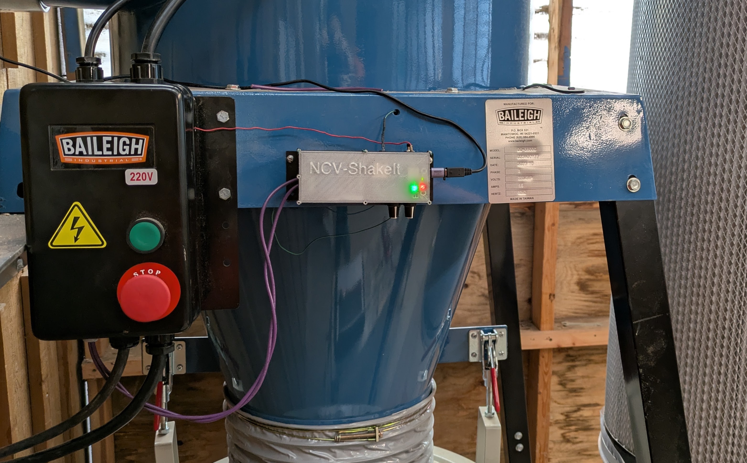
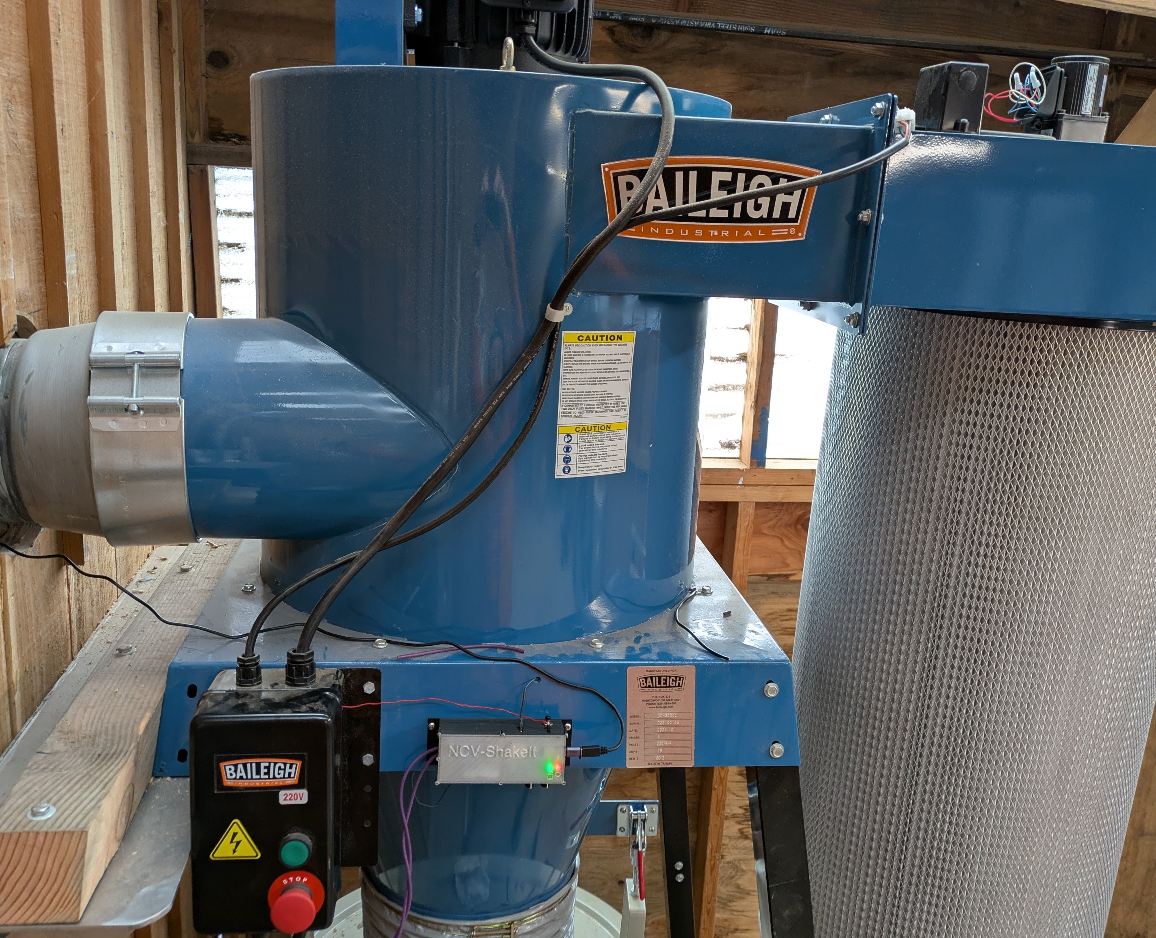
I’ve been looking for compelling electronics projects to hone my skills in firmware development, electronic circuit design, printed circuit board design and 3D generative design. A friend approached me with a problem at a large woodworking shop that had a few interesting features, so I decided to design a device for him. In the woodworking shop there is a large dust collector (with a 3 Phase Motor) that gets run a few times a day. When that large motor shuts down, a smaller two phase motor should shake a large dust filter after a long pause (~10min). The long pause allows the large motor to stop spinning but also allows an interval where somebody could turn the dust collection system back on which then delays the filter shaker from running. The filter shaker should be run occasionally, but not more often than necessary to extend the filter life. Running the filter shaker allows the whole system to run more efficiently as sawdust quickly clogs the filter.
Requirements to think about:
- How do we determine when the large 3 phase motor is running and has finished running? How tied into the existing system do we want to be? I’d rather not hook into an AC system directly.
- Solution: I found a number of techniques for non-contact detection of AC voltage and current. There are good, but expensive inductive current sensors that surround an AC line to measure current running through. Alternatively, I found an elegant non-contact voltage solution in this great Instructables Project. That project details making a non-contact voltage (NCV) detector that is similar to the small pen like devices that electricians use to check if a circuit is hot. If this circuit can detect the electromagnetic field (EMF) of a hot AC line this would be an elegant solution requiring minimal parts (a high value resistor and a section of antenna wire).
- How do we turn on the 2 phase motor properly?
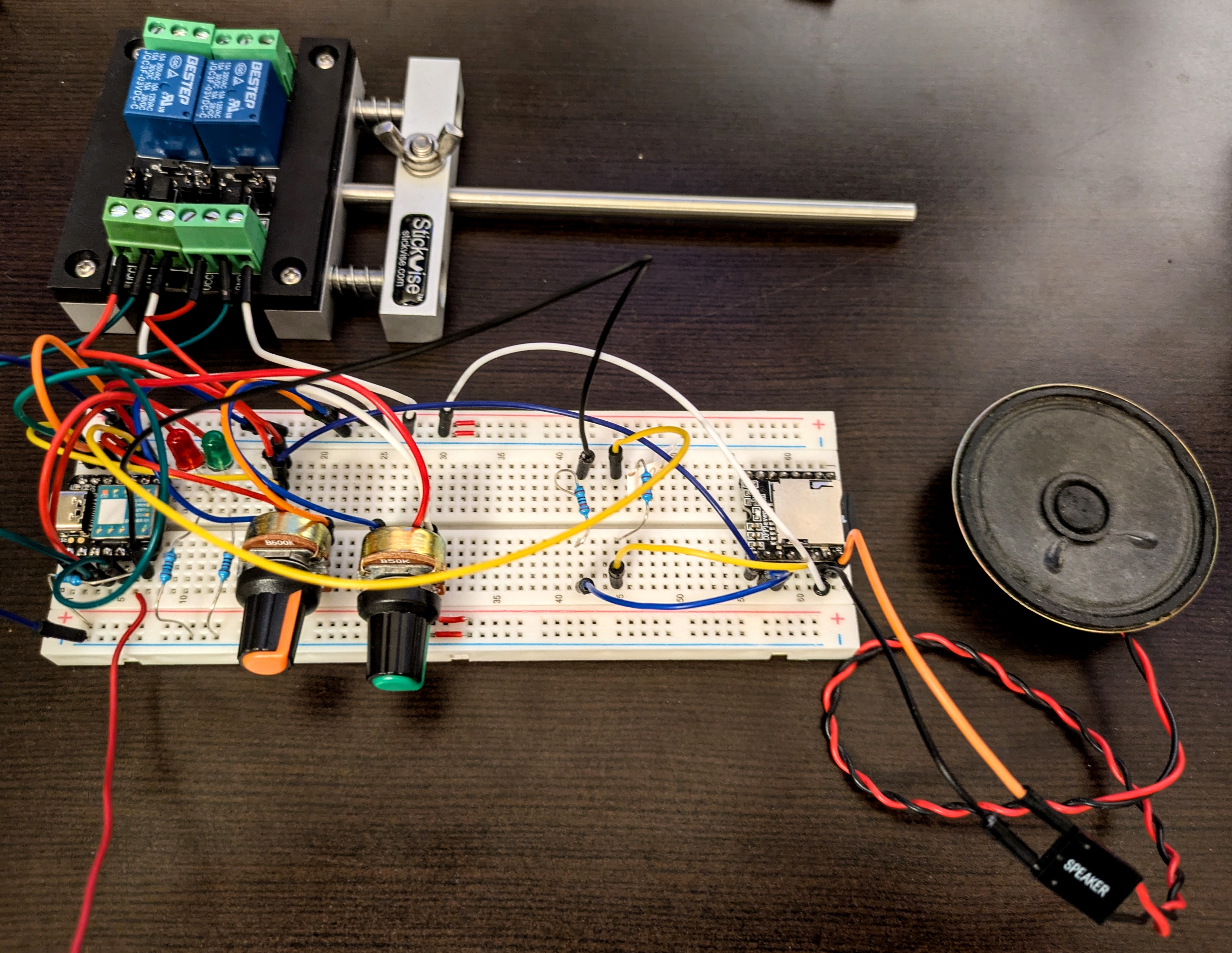
- Solution: I did some research and it sounds like people are ok using two relays to switch two phase motors. There are special relays for this, but I have two low voltage triggered relays available.
- A scheduled shaker motor run should be delayed by any dust collection system run during the spindown and wait period
- Solution: Hmm, finite state machine?
- A run of the dust shaker should be immediately stopped if the main motor starts up.
- Solution: Yes, probably finite state machine.
- The spindown and wait period should be about 10 minutes
- The minimum main motor on time should be 5 seconds or so to prevent unnecessary runs of the dust shaker
Brainstorming features based on the requirements:
- It would be good to make it easy to know the status of the machine. Visual feedback for one, but also it might be nice if it gave some gentle audio warning that a surprising and loud vibratory motor is about to start. I will show system status with LEDs and make a gentle alerting sound by playing mp3s. I’ll use a DFRobot Mini Player for the mp3 playing.
- Allow the user to easily adjust (using rotary potentiometers):
- The amount of time the dust shaker motor stays on for. They will be able to see the amount of dust falling off of the filter and gauge the amount of time is appropriate.
- The sensitivity of the EMF detection by the NCV circuit. Think of this like the squelch knob on a VHF radio on a boat or airplane.
- The volume of the audio alert that will be played to let people know the filter shaker motor is about to run.
- After talking about possible features with my friend and showing him the first prototype, he requested a button that would start the motor manually. Sounds good. This button ended up enabling some other user configuration options. See the notes about the AceButton library below.
Getting Started
I jumped right in with the prototype board design. There were a few parts that I wanted to prototype first in isolation to understand them better:
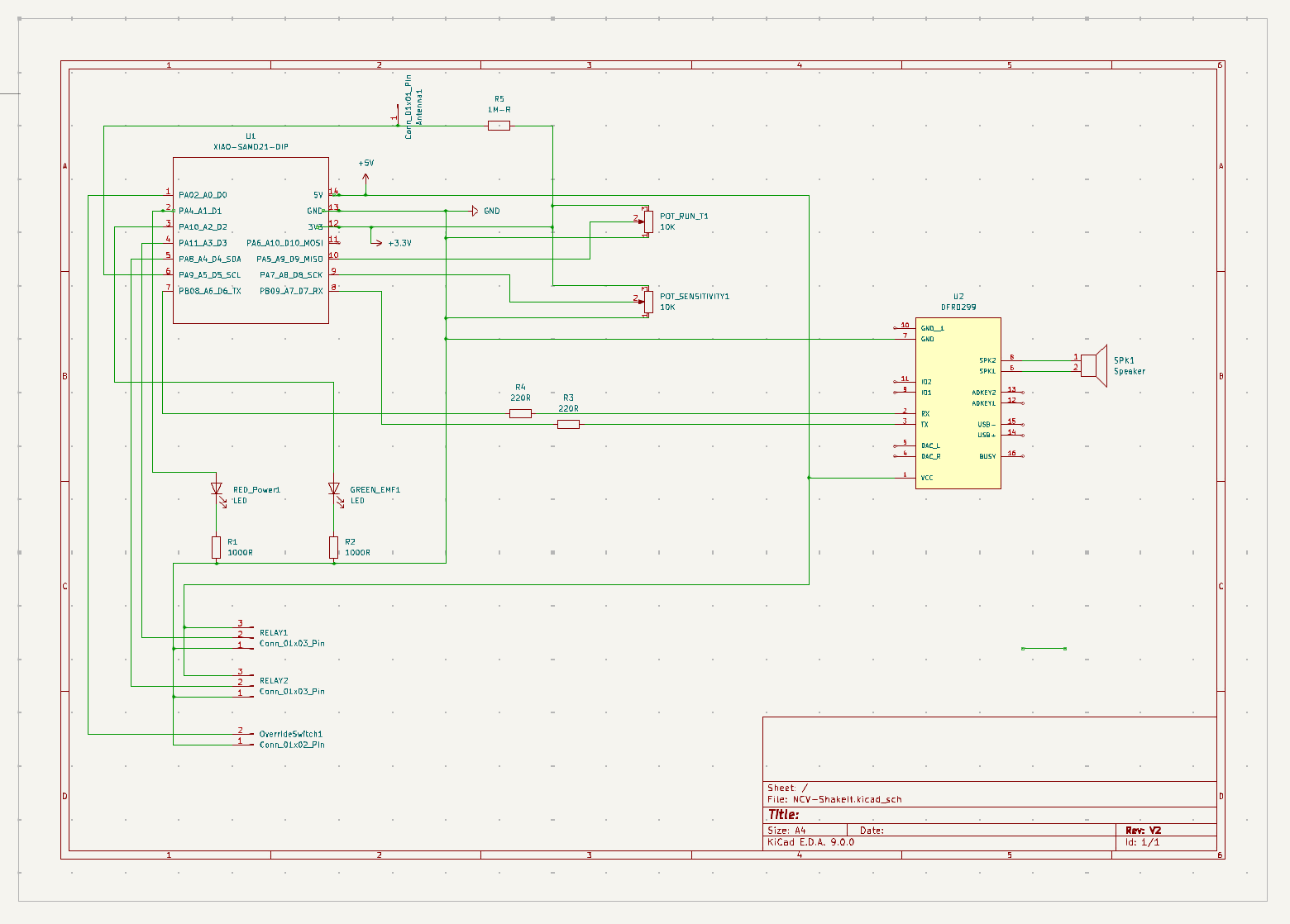
Using the Seeed Xiao SAMD21 microcontroller - I had used it for a couple of quick projects a long time ago, but needed to read up a bit to get my head around it again. It’s a good, inexpensive microcontroller. I was able to easily set it up in my preferred development environment VSCode with PlatformIO.
The Non-contact Voltage detector - This is the most unique part of this project. The Instructable I based the code on was excellent. The most important change I made to the code was adding a user adjustable sensitivity knob. The algorithm is very sensitive to how the antenna wire is set up and other environmental factors. The adjustable knob makes it easy to dial in the sensitivity for the actual physical installation.
Controlling the DFRobot Mini Player - Finding the right documentation and figuring out the serial protocol was a little bit of work.
The initial firmware for the new device proved out the functionality, but it quickly became apparent that a proper finite state machine would be useful for handling the transitions between the possible states of the machine. The states I ended up settling on:
  enum State {
      LISTENING,      // Waiting for EMF detection
      EMF_DETECTED,   // EMF detected, monitoring duration
      SPINDOWN_WAIT,  // EMF no longer detected, waiting to activate
      ACTIVATING      // Playing music and activating relays
  };
Other notable features
- Ace Button Library - I added one physical button to the project. At first, the button was just to manually initiate the relay on cycle. Soon I realized, it would be nice if the button could do more. I’ve used the AceButton library in the past, and it made adding multiple functions to the same button easy. I ended up with:
- single click - Immediately start the relay on (filter shaking) cycle
- double click - Play a random song
- long press - Capture the position of the the potentiometer knob that usually sets the relay on time and set that as the music volume level.
- Potentiometer knobs - These are set up as normal voltage dividers which provide convenient user inputs when checked via the SAMD21’s onboard ADCs.
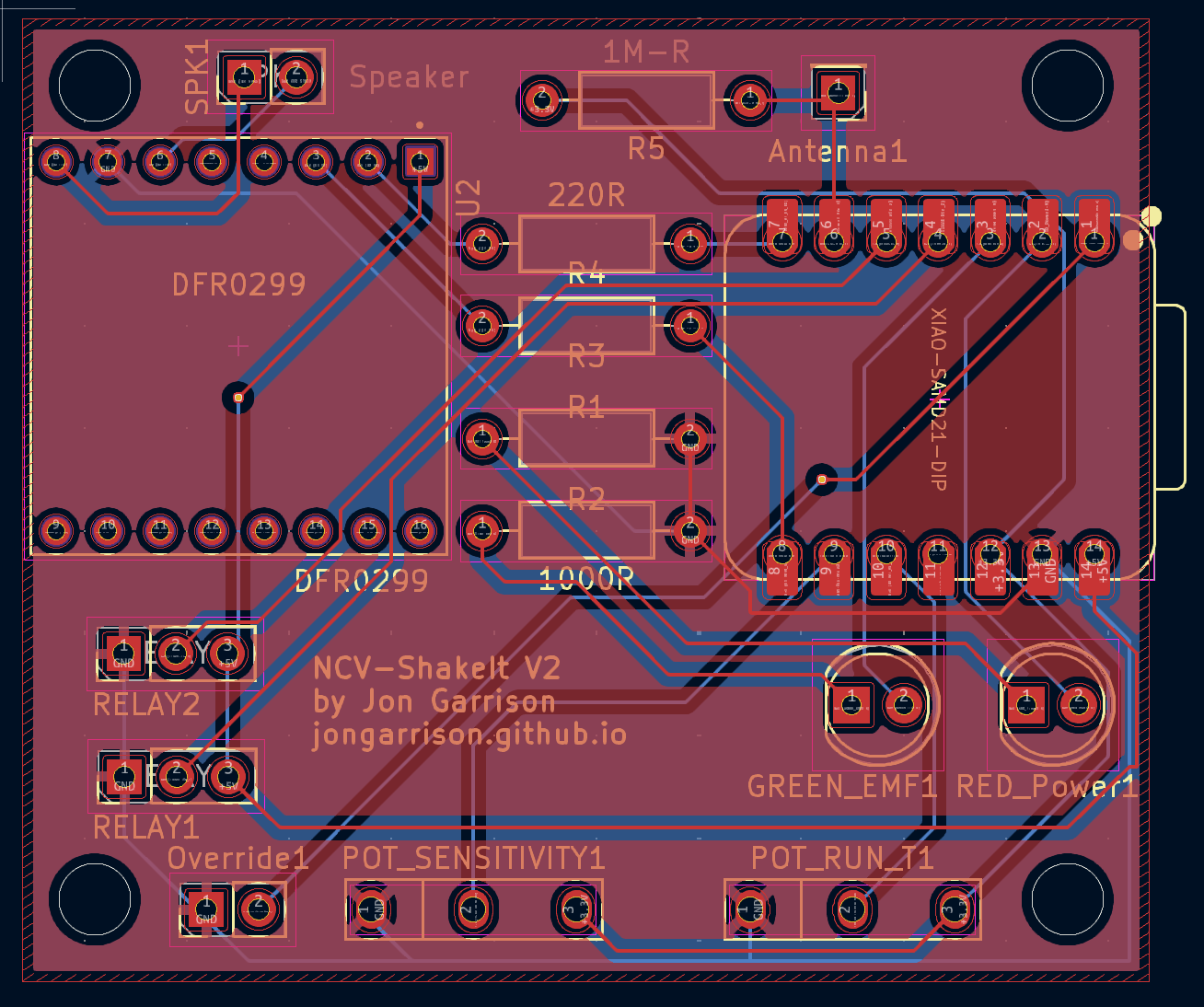
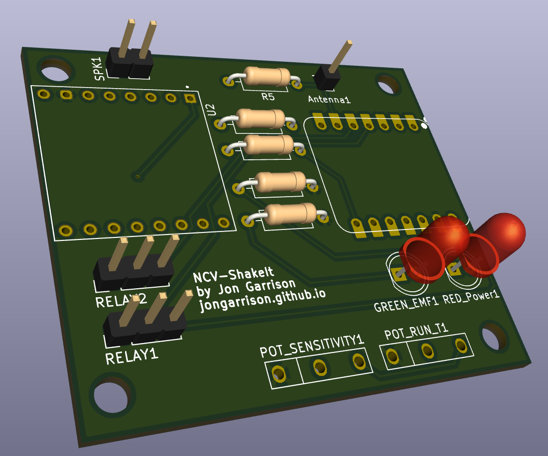
PCB Design!
I saw an excellent presentation at CrowdSupply’s 2024 Teardown Conference about the current state of KiCAD. I was very impressed and hoped to get to use it for a project. Well, this is the project!
I was very lucky to have some helpful PCB design advice from Robin of Island Underground.
I started with KiCad by watching a number of youtube videos. This one was a good quick overview that I re-watched many times. One particular aspect of that video that I thought was helpful was the design of a custom footprint. I ended up using this for the potentiometer footprints.
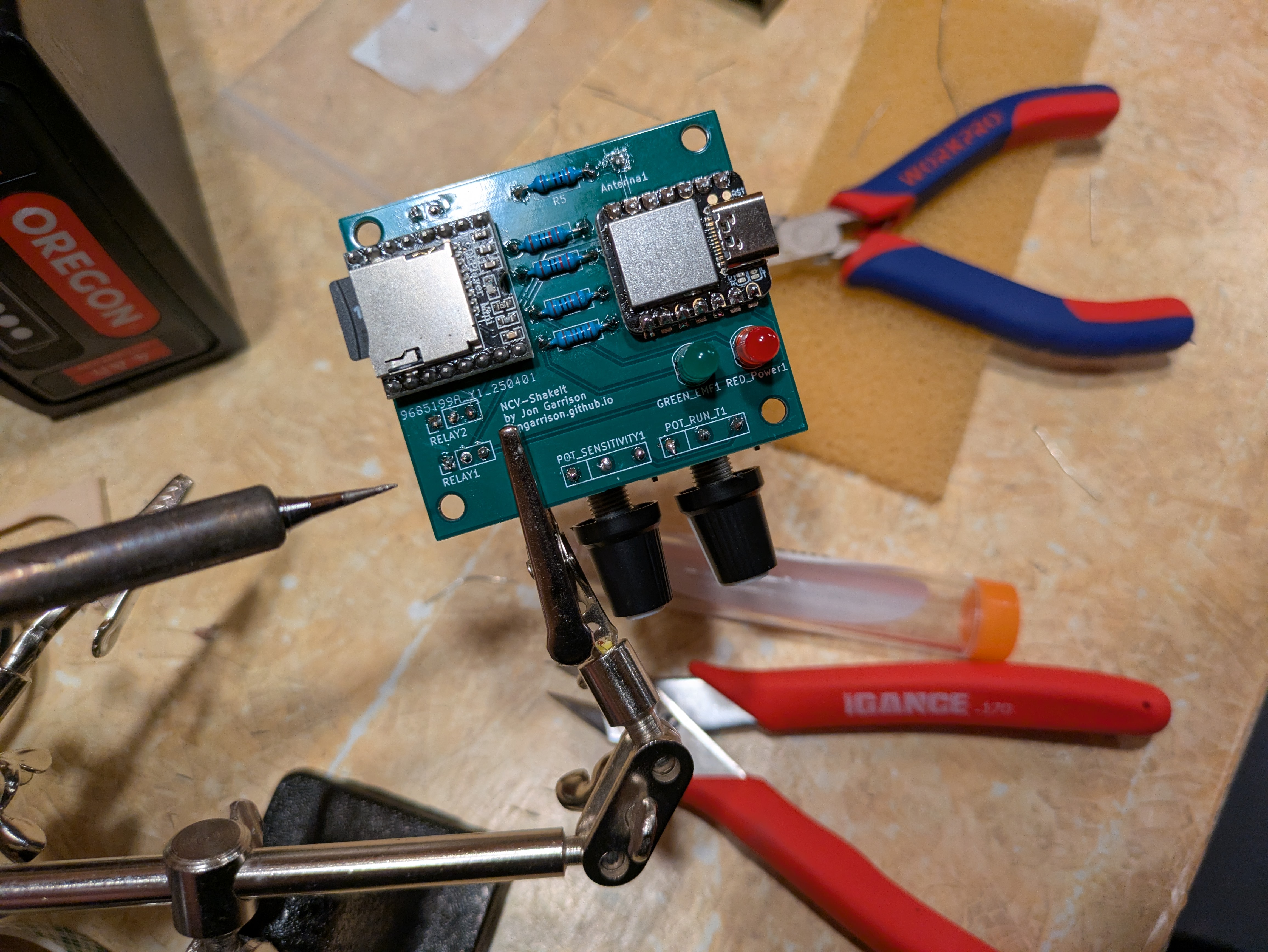
I followed Robin’s advice to use JLCPCB.com. Their website, prices and delivery time are amazing. I started uploading my gerber files around 10:30pm and production was started a few hours later. I had the pcbs in my hand 7 days later!
![]()
Also, Robin’s prediction that I would have several changes that I would want to make to the board before it arrived proved to be true. Ha! He was certainly correct, but this first version of the board has proven to be serviceable. I left the pins untrimmed underneath both the microcontroller and the DFRobot Mini Player. This proved useful for connecting some last minute fixes. For example, I routed one of the speaker terminals to the wrong pin! This was an easy fix.
Enclosure Design (Rhino3d/Grasshopper)
For the last couple of years, I’ve been using Rhino’s Grasshopper tool for 3D design whenever it seems appropriate. There is a significant learning curve, but it feels very much like writing good modular software to me. I enjoy defining the inputs for a 3D object and then feeding those inputs into various algorithms until a solid, real life, useful object emerges. Also, by developing 3D objects in this way, designs can adapt as project constraints change.
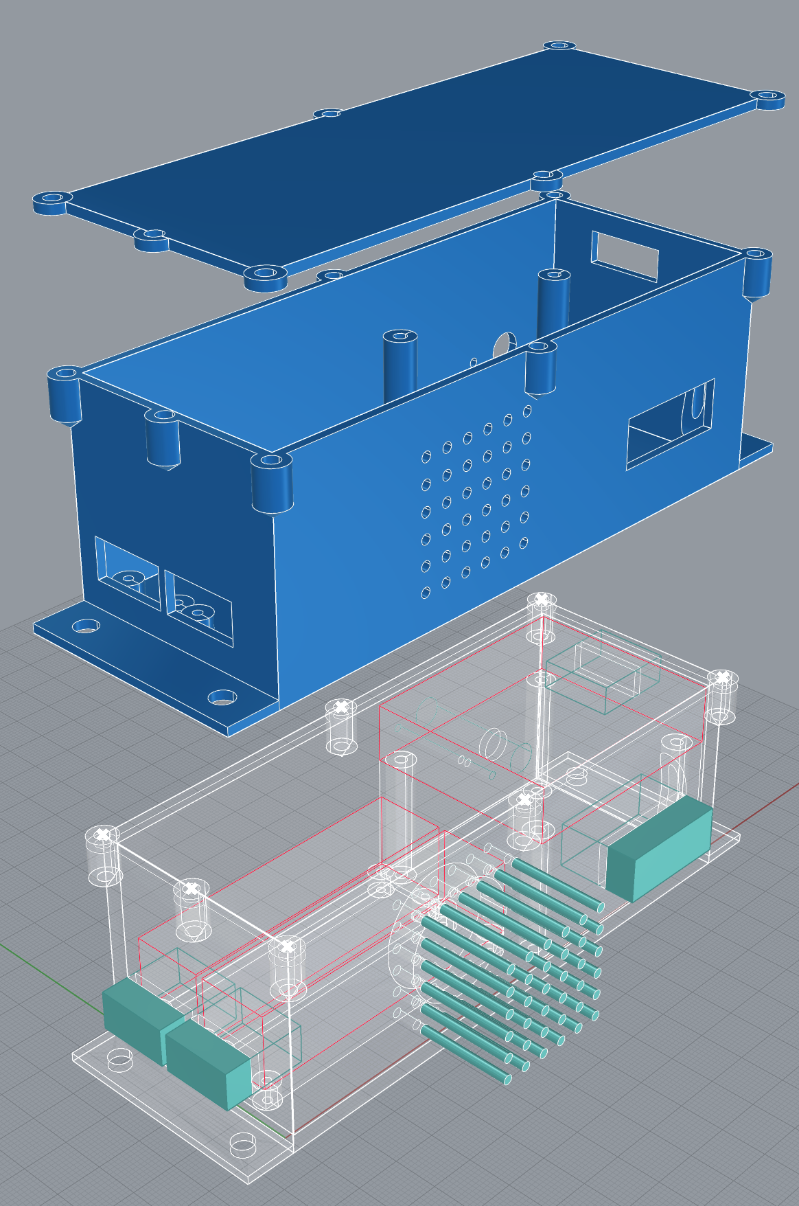
For a very high level overview of how I created this enclosure, I’ll describe the general flow of the thinking in the Grasshopper layout below. Also, you can look at the Grasshopper file itself if you want to dig deeper.
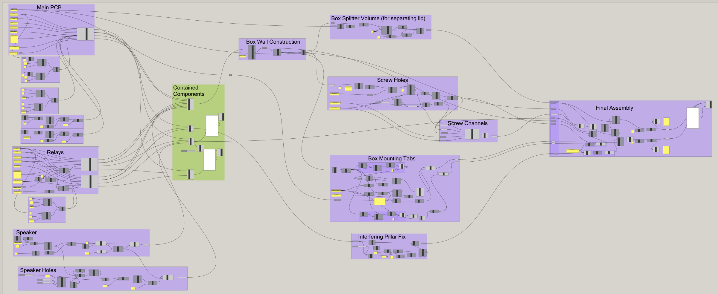
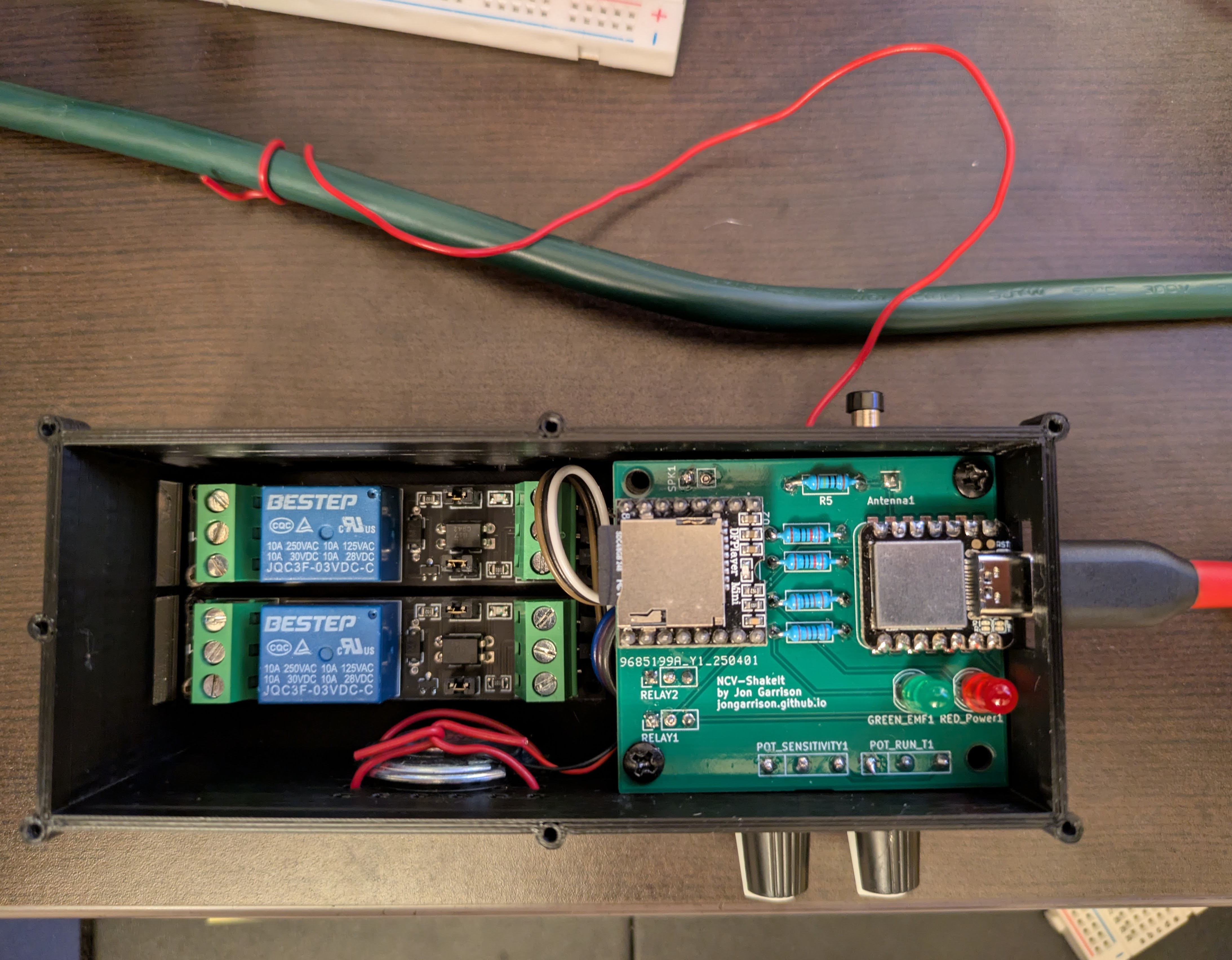
On the left, I am defining the various components that must fit inside the enclosure. There are 4 major components that take up space:
- The custom PCB
- Two relay boards
- A small speaker
I created a reusable Grasshopper cluster that consistently keeps track of a few things for each major component:
- The X/Y dimensions of the board
- Positions of screw holes and the associated sizes
- The heights of the protected regions above and below the PCB board itself
- “knockout” geometry associated with each component. These are shapes that must protrude through the enclosure (for example the push button, relay terminal access, potentiometer knobs…)
Once I have this information described for each major component, I was then free to arrange the components in various ways to see how I wanted them to be positioned relative to each other. The algorithms for the construction of the case can then flow from those input constraints and I can see how the box takes shape as I change things. I guess there is a huge leap there, how is the box actually made? Well there is a lot to that, but imagine starting with a bounding box that contains all of the major components. Now put an offset bounding box around that to simulate the thickness of the plastic walls. And keep going…
Some highlights of box construction
- The screw pillars automatically position themselves underneath each major component’s screw holes and extend down to the floor of the box.
- The box lid is sliced from the sealed box after the screw guides are automatically positioned around the top perimeters. This means that the pass through screw holes in the lid are essentially created for free.
- Side note: In Grasshopper, some algorithms can get bulky really quickly in a way that code can solve much more elegantly. As I was designing the lid retention screw features, the Grasshopper approach became ungainly and I switched to using a Python component which only needed 49 lines of code to do what it would take an Ikea warehouse of grasshopper nodes to achieve.
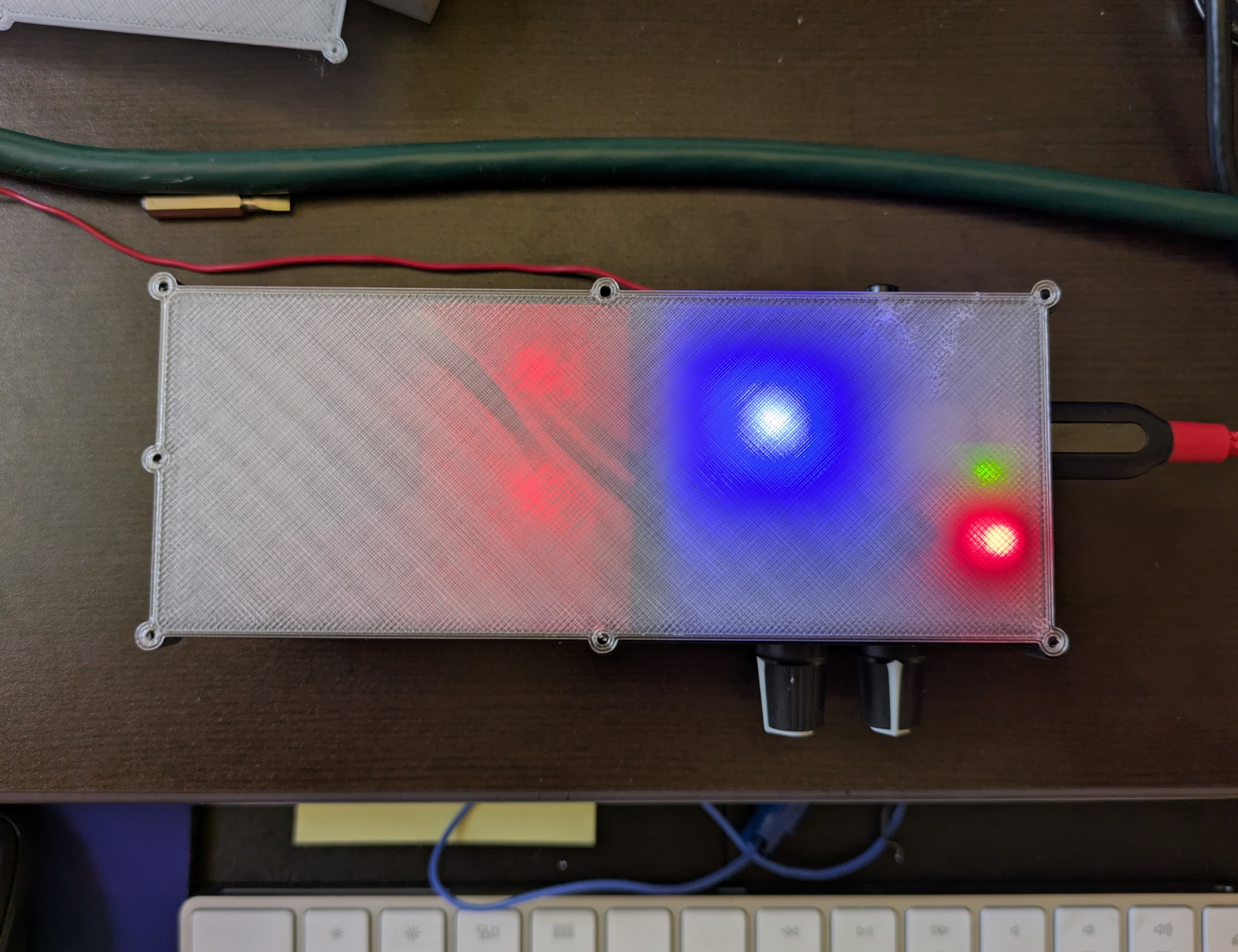
- Embossing text on the sides of the enclosure was a fun side mission. With 3D printing we have to be careful with overhangs. I found a general purpose solution for the text was to extrude it away and up at 45 degrees away from the case wall. This allows any text to be printable on a side wall. See the first picture above for an example of this (“SQ” and “RUN T”).
- I think that some of the concepts I captured in this Grasshopper project will continue to have value for future enclosure projects.
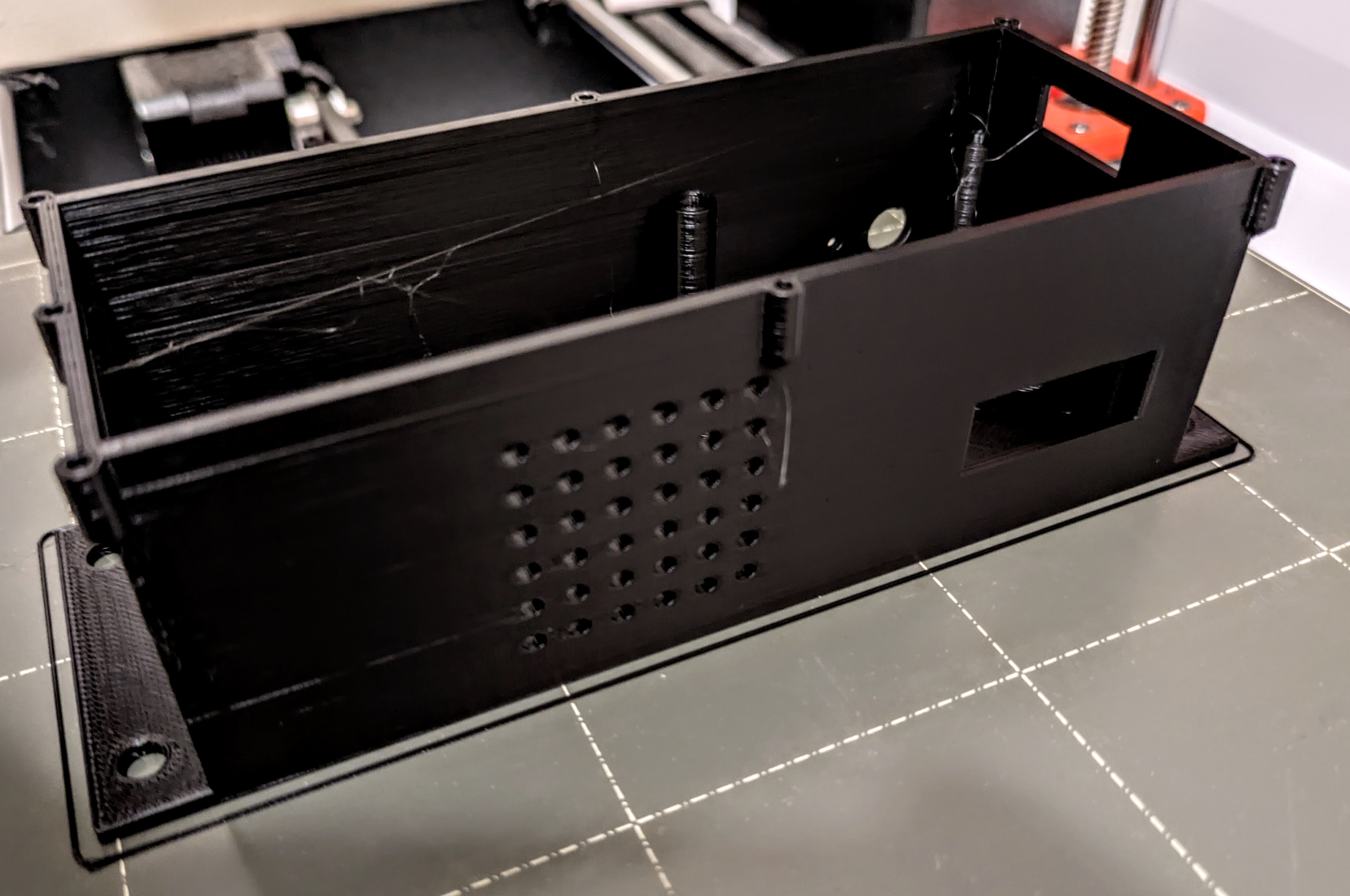
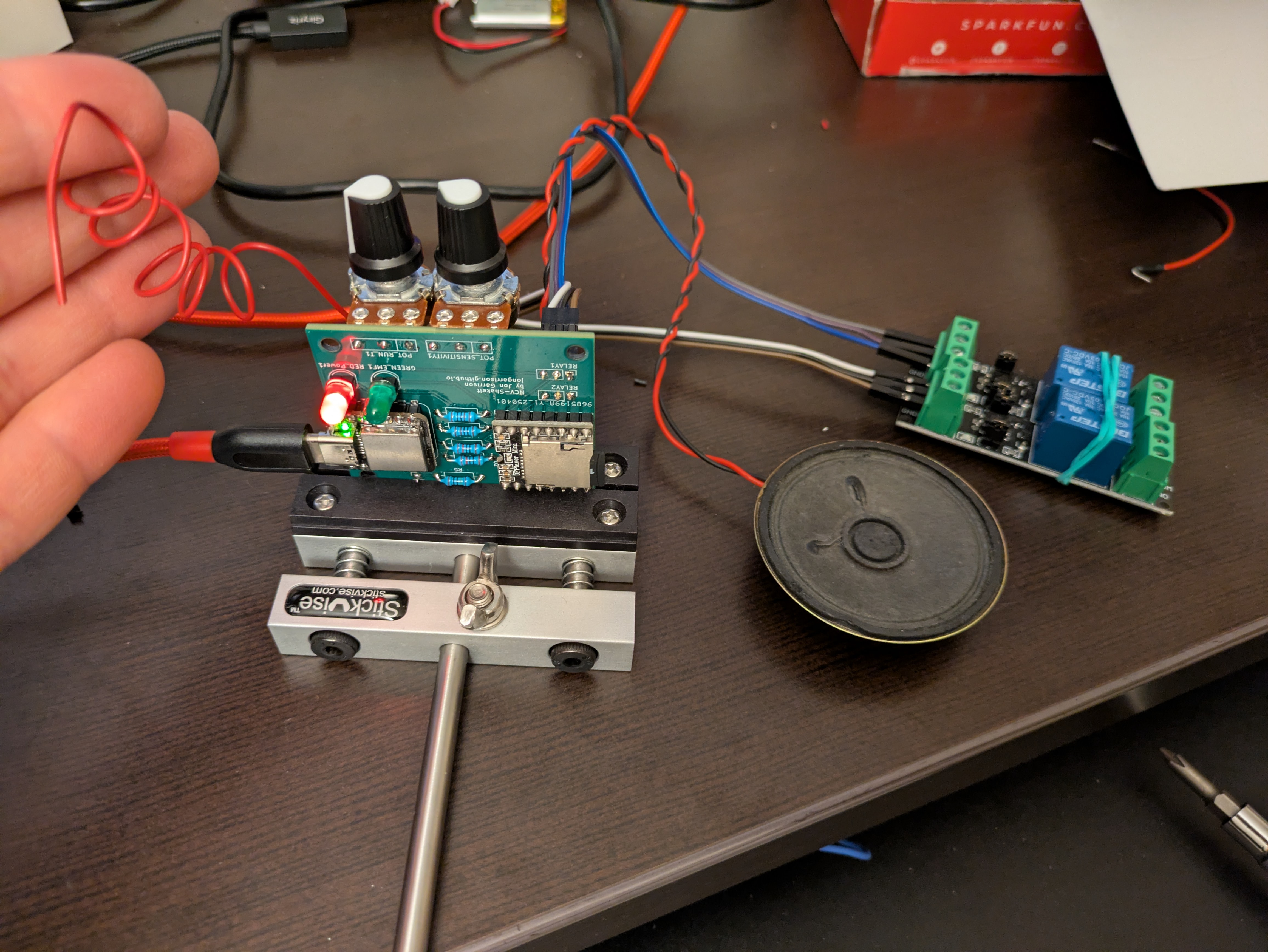
Coming Together…
Next Steps
I would really like to develop another “hardware in the loop” testing machine to test this machine. This machine has been tested for a while on my desk, but I would really like to run it through its paces a few thousand times over a few months to see where it fails. I have developed this type of machinery in the past and it would be good to verify the reliability of this device.
Some Features of a “Hardware In The Loop” Testing Machine:
- Switch AC power on and off to the monitored AC line
- Verify that the machine indicates that EMF is detected
- Verify that the relays were switched on after the correct interval and then stayed on for the right interval
- Verify that the music played?
- Verify that it responds to adjustments of the knobs and pushes of the button
- Provide reports for testing progress
Let’s Talk
This was a very interesting and rewarding project to work on. Despite the simplicity of the circuit, it presented enough challenges to be a compelling build. My appreciation for designers of clean and simple electronics is only heightened by this project. The simplest choices can lead to unintended complexity and compromise. Things like the height of these particular potentiometer knobs led to me flipping them to the underside of the board. That solved a problem, but then required reversing the mapped ADC values in the firmware and making sure the pcb could be maneuvered down into the enclosure. Balancing compromises to deliver useful functionality is a worthy challenge.
It would be easy to go into a LOT more depth on this project. I’ve shared all of the associated design and code files which can provide significant detail, but I’m also happy to talk more about it. Feel free to reach out to me on LinkedIn if you think I could help you on a project or just to talk about this one!